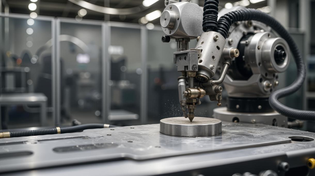
What is Side Milling?
So, what exactly is side milling? We can strip it back to its core idea. Side milling is a machining job where we use the side of the cutter, its edge, to machine a workpiece’s vertical surfaces. Imagine using the edge of a spinning disk to shave down the wall of a part. That’s the basic idea. The idea isn’t to drill a hole or face off a surface. We’re creating flat, vertical walls. We’re getting precise widths. We’re machining critical features like steps and slots. It’s a key part of professional machining.
How it Works?
The Tool & The Workpiece
The process of side milling is actually quite straightforward, but any machining operation involving cutting tools demands exceptional caution from engineers—safety comes first.
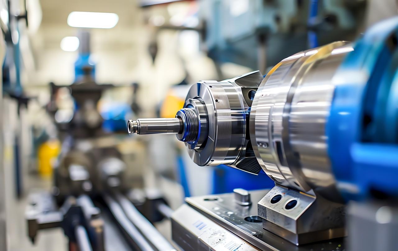
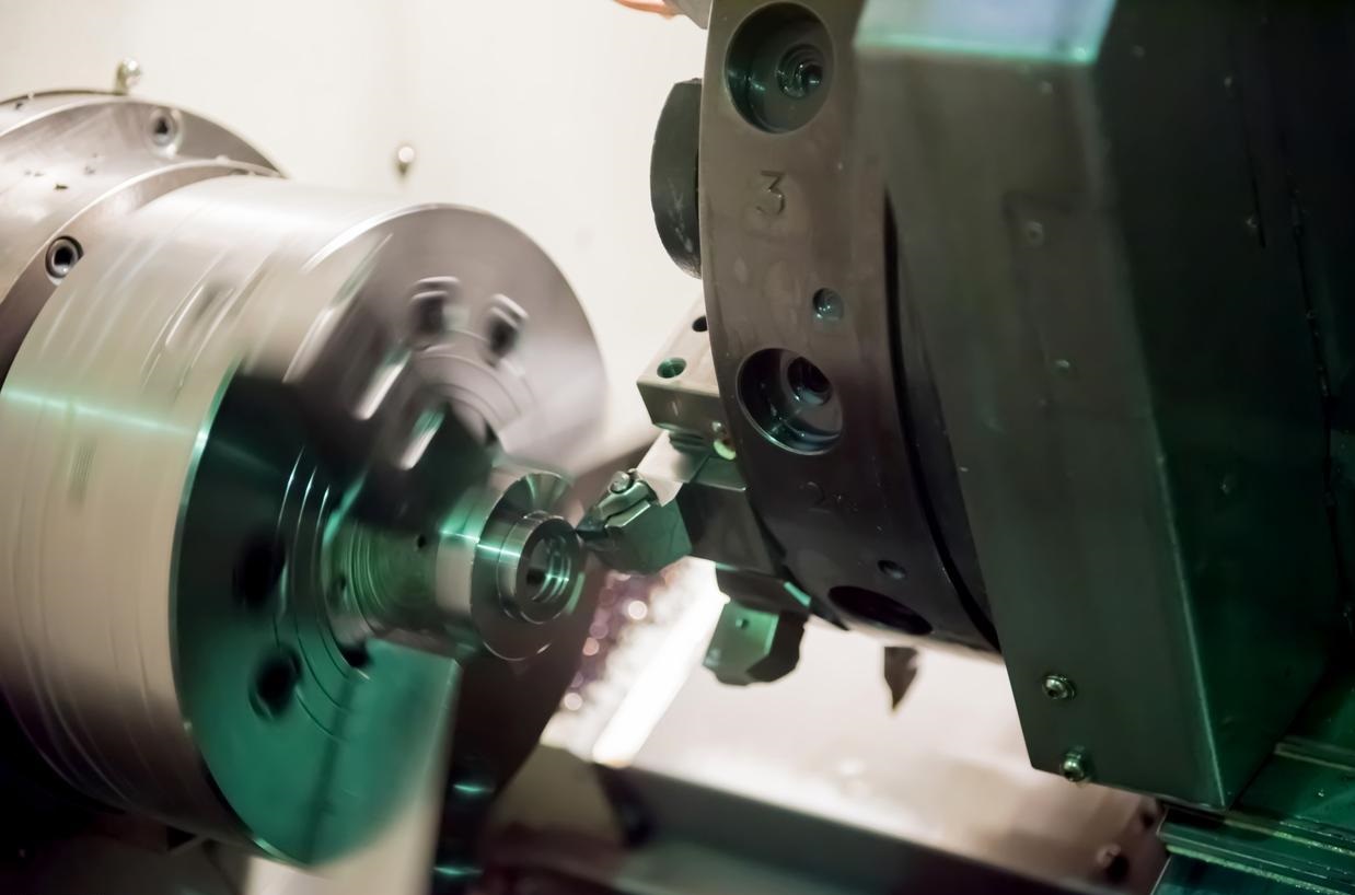
The primary task is to ensure the rotating tool is securely locked onto the spindle of the CNC machining center. It must be emphasized that rigidity requirements are non-negotiable. Any looseness will lead to machining errors.

Next, secure the workpiece—such as an aluminum blank for automotive components—to the machine table using a vise or fixture. I’ve witnessed cases where neglecting this step resulted in catastrophic failure of the entire milling operation. Understand this: the success of side milling hinges entirely on the workpiece’s absolute stability.
Now the machine can be started. The spindle spins the tool at high speed while the worktable slowly feeds the workpiece horizontally toward the tool’s cutting edge. The tooth profile of the cutting edge engages the material through a series of rapid, precise bites, shearing it into fine chips. Each feed removes a precisely measured layer of surface, transforming a rough face into a brand-new, smooth, and extremely precise vertical wall. This is the essence of side milling—controlled mechanical erosion.
Key Characteristics of Side Milling
It’s really important to understand the basics of side milling if you want to tell the difference between basic machining and true precision manufacturing. This goes beyond just cutting metal; it’s about being able to predict and control the outcome of the machining process.
When we’ve done side milling in the past, we’ve found three main things that matter. To be honest, these things decide whether a project will be a success or a failure.
Surface Generation
As we know, the main result of side milling is creating flat vertical surfaces. But there’s no guarantee that every cut will be smooth. It depends on things like the tool you choose, how fast you feed it, and how rigid the machine is.
If you use brand-new, sharp end mills with the right settings, you can get surfaces that are really smooth. NOBLE often meets automotive component surface finish requirements straight after machining, so you can cut out secondary finishing operations. This efficiency is at the heart of NOBLE’s professional machining philosophy.
Dimensional Accuracy
This is exactly where side milling comes in. We find that side milling is the best way to make sure the width and parallelism is spot on on both sides.
Imagine a block that’s got to stay a certain width all the way through. We’re not just hitting the target dimensions, we’re nailing it.
CNC machining processes make this repeatable. One time, when we were machining a custom-designed actuator housing for a client, it was really important that the width was spot on all the way across. This is just one of those standard things you have to do at the NOBLE factory.
Tool Engagement
When you’re doing side milling, the main cutting force goes out from the centre. When you’re cutting, the tool is basically being pushed away from its centre. This force makes the tool bend a bit. This is more common with slender end mills. If you ignore it, the tool will bend away from the workpiece wall, which will mess up the dimensions and end up with faulty parts with too much taper.
NOBLE engineers deal with this in three ways: picking the shortest, most rigid tools; adjusting feed rates; and sometimes using cycloidal milling paths to reduce tool stress. It’s a practical balancing act between metal cutting theory and the actual physical properties involved.
Common Tools Used for Side Milling
Choosing the right cutting tool is more than just a step in the machining process; it’s a critical decision that determines whether the entire face milling operation is a success or a failure.
Here at NOBLE, we get that picking the wrong tool can mess up your machining accuracy, efficiency and cost. Our engineering department has a huge range of cutting tools, each one picked out by our experts to make sure we can deliver top-notch machining.
Here’s a simple comparison of several types of knives. Hope this helps!
| Feature | End Mills | Shell Mills | Side Milling Cutters |
| Description | Versatile, teeth on end & periphery | Large diameter, mounts on arbor | Narrow, for straddle milling |
| Primary Use | General purpose, slots, contours | Wide surfaces, high stock removal | Parallel surfaces, simultaneous machining |
| Typical Size | Small to medium | Large | Narrow |
| Key Advantage | Versatility, accessibility | Stability, efficiency for large areas | Dimensional accuracy for parallel features |
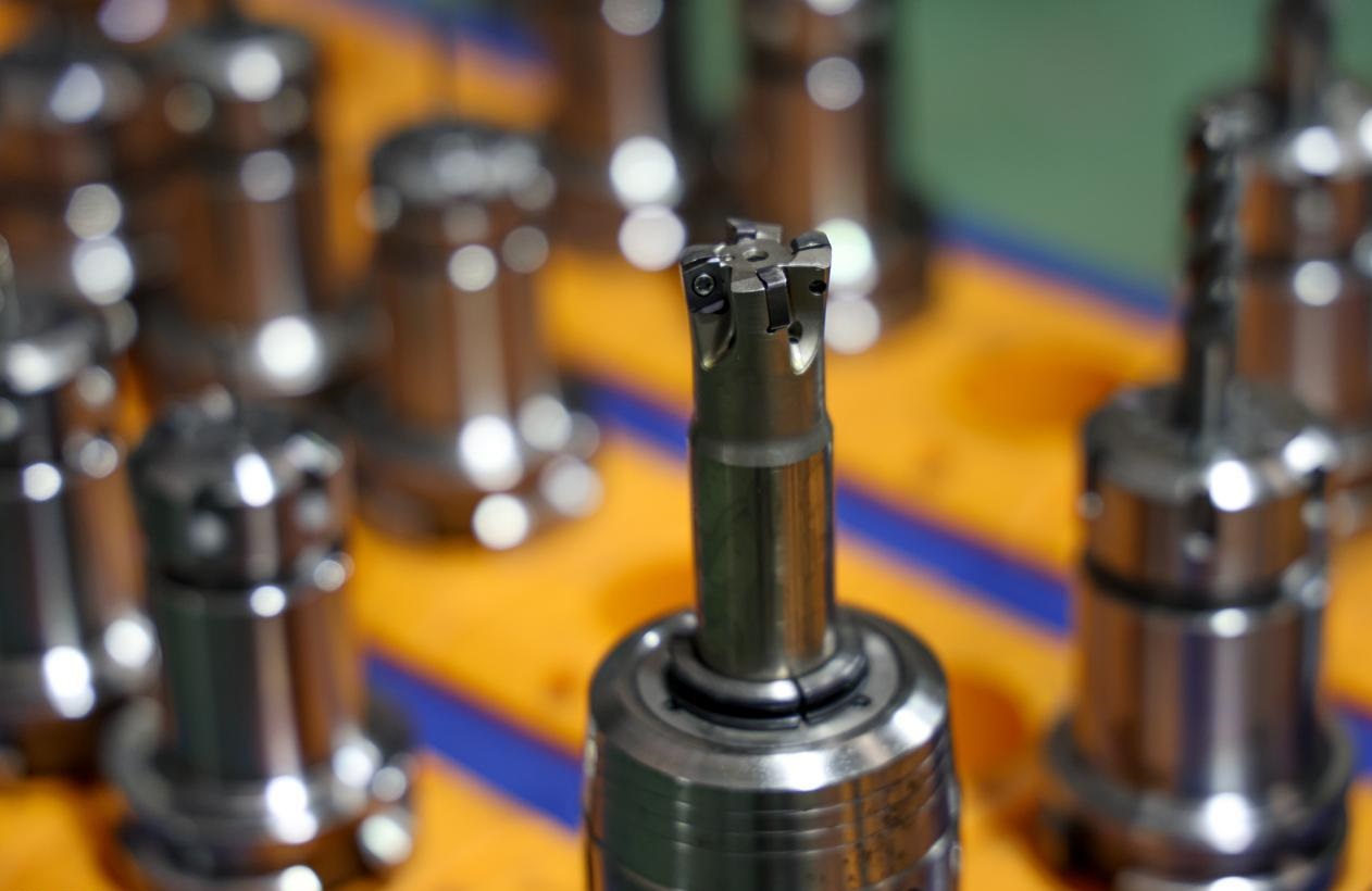
End Mills
End mills are definitely the go-to tools for side milling operations. Their defining feature is the cutting teeth positioned on the face and along the edge.
We use strong square end mills for accurate angular machining of workpieces, making sharp 90-degree right angles. When we were machining aluminium automotive intake manifold prototypes, we chose standard four-flute end mills to quickly establish the main reference walls. This approach keeps cutting rates high while delivering surfaces that are really smooth – sometimes you don’t even need to do any post-processing.
Shell Mills
When we’re milling larger components or need to cover a lot of ground, we switch to shell mills. A shell mill is basically a large cutter body mounted on its own tool holder. When you’re doing side milling, it’s just the edges on the sides that are cutting.
The shell mill is pretty big, so it’s really stable. I’ve seen our engineers use it to make full-height cuts on steel mould bases in one go, which is way better than using smaller end mills and doing it in multiple steps. This is really important for our high-volume precision manufacturing projects, where cycle time and tool life are key metrics.
Side Milling Cutters (Straddle Milling)
This is a more professional and classic approach. Side milling cutters are pretty narrow milling cutters. They’re most useful for cross-milling, where you can attach two cutters to the same tool holder, spaced exactly how you want. This setup lets you machine two parallel vertical surfaces at the same time, making it super efficient.
Recently, when they were mass-producing graphite electrodes, NOBLE engineers used this method to make sure they could reliably machine multiple sets of perfectly parallel fins.
Types of Side Milling Operations
The idea behind side milling is pretty simple, but how it’s done can differ quite a lot depending on the end goal.
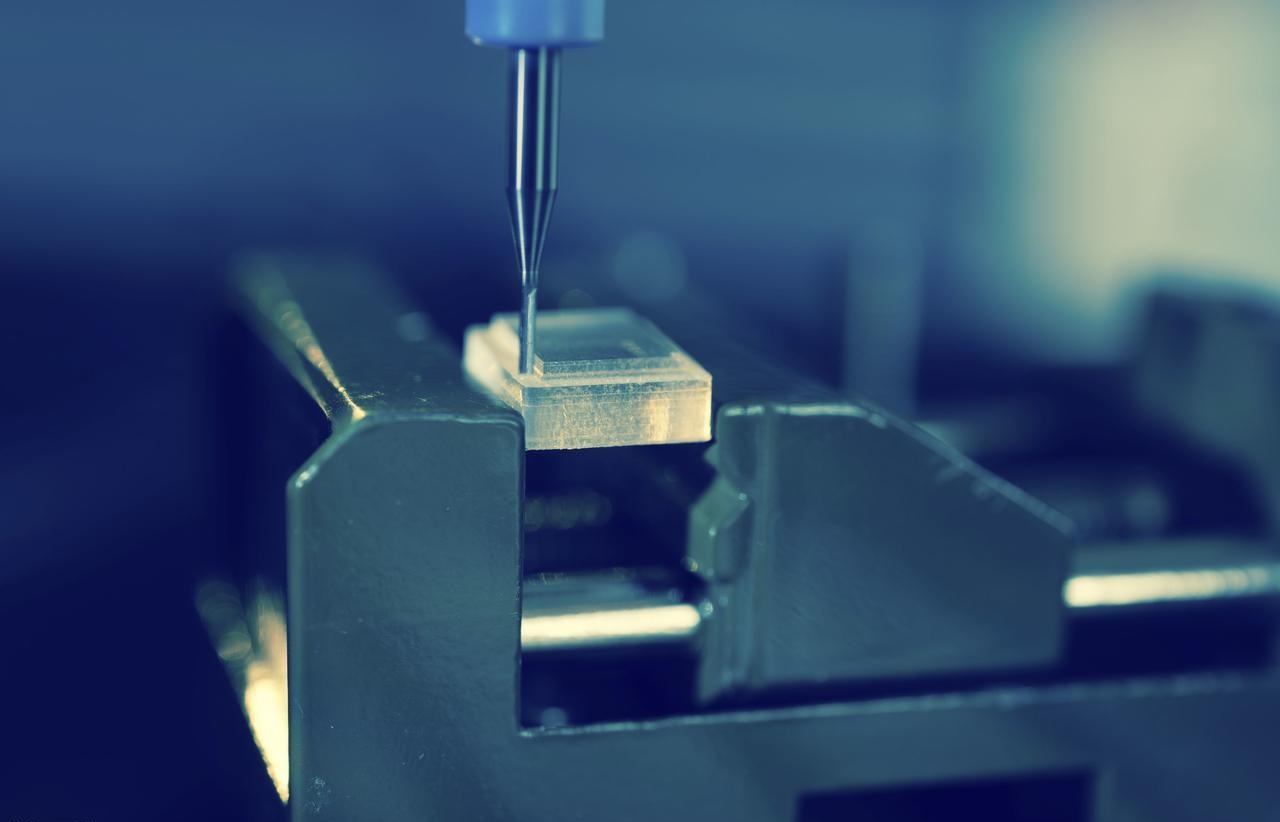
Plain Side Milling
Plain side milling is the most basic and simple machining process. One tool processes a vertical surface through a single linear feed. You can think of it as trimming the edges of a wooden board to make them straight and square. This method is simple and efficient for most basic contour machining. Engineers often use it for custom machining individual parts or for preliminary trimming of raw materials.
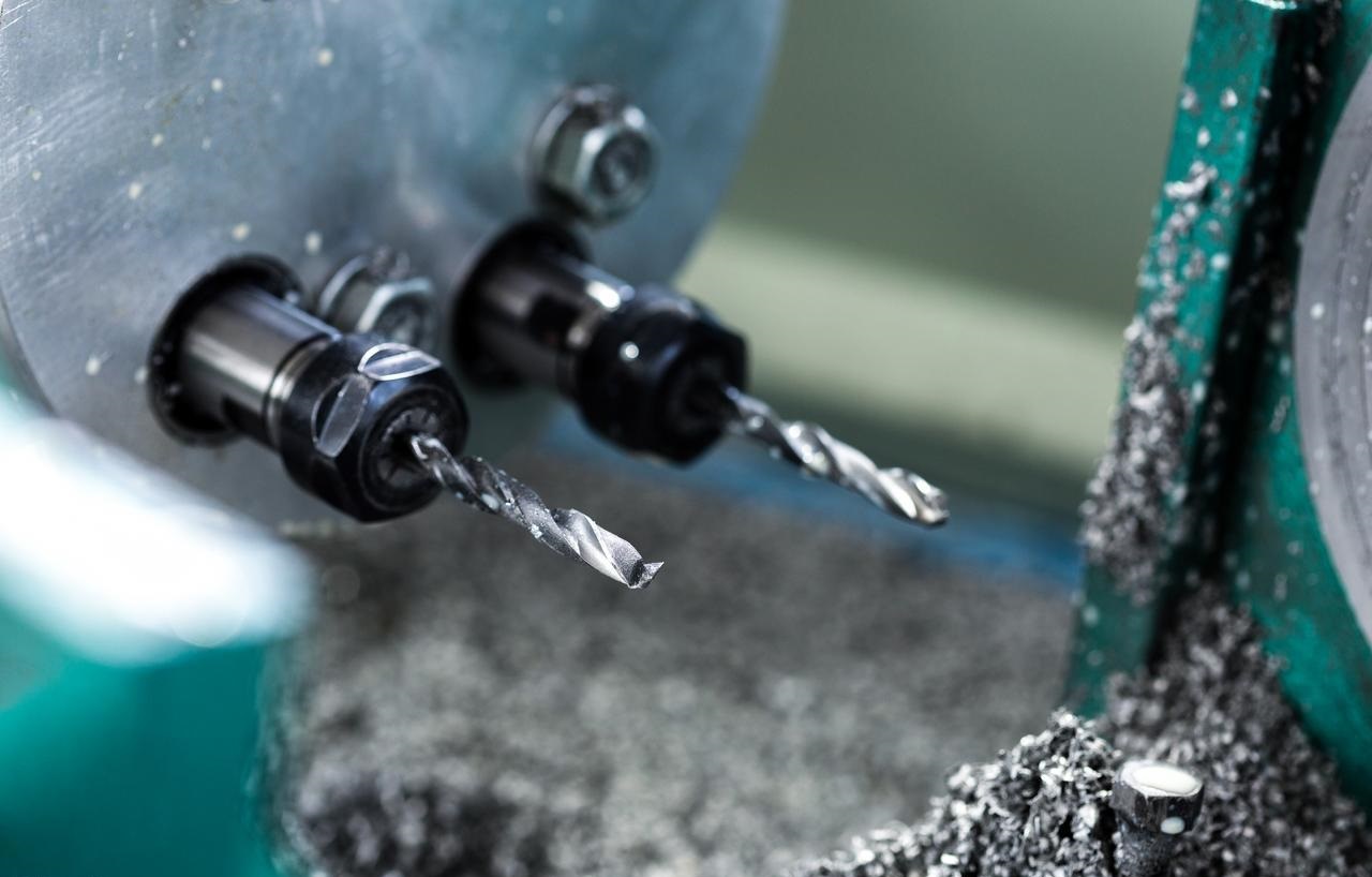
2. Straddle Milling
Now, we’re moving on to a more efficient and precise machining technique. When we do straddle milling, we lock two side cutters onto the same tool holder, and we use positioning collars to figure out the final width. With one clean cut, they can machine two parallel vertical surfaces at the same time during side milling.
It’s pretty clear how they’re better: the distance between the tools directly affects the width of the workpiece, making sure it’s always parallel throughout the side milling process. This is perfect for machining hexagonal flats with custom fixtures or for precisely machining workpieces to specific dimensions without having to reposition them.
3. Gang Milling
Group milling technology takes the idea of simultaneous machining to the next level. Picture this: lots of cutting tools of different diameters, widths and profiles all mounted on one spindle. This setup lets us do side milling operations on different surfaces, slots and contours all in one go.
Setup is a bit of a headache, but it’s worth it for big-time production. When you’re making lots of special parts, like those multi-step machined medical implants, combination milling can really speed things up.
Practical Applications of Side Milling
You find side milling everywhere in a modern machine shop. It’s not some abstract concept; it’s the daily bread-and-butter work that transforms raw material into functional components.
Squaring Up a Block
This is normally the first step in machining metal blanks. Engineers need to process rough castings or billets into standard cubes that are exactly the right size. Then, using a series of side milling operations, all six faces are machined to establish the foundational reference for all subsequent processes.
Creating Steps and Shoulders
We often need to machine vertical surfaces to create steps on parts (such as mounting flanges or locating features). Side milling operations cleanly remove material to form sharp vertical shoulders.
Slotting
When you’re slotting something, the cutting tool only touches the end of the slot and the sides. How good the slot walls are depends entirely on how good the side milling is. The two vertical side walls are formed by the outer edge of the cutting tool. The slot width depends on the tool diameter.
Contouring
By moving parts along multiple axes under the side milling machine, you can shape complex vertical contours on components. This is far from simple linear machining—we can do curved wall machining, precision pattern engraving, and organic shape forming. This capability is really important for custom machining parts like automotive-specific impellers or mold cores.
Parting Off
This is the final, more intense application. We use a thin slitting saw, which is a special type of side mill, to cut a finished part away from the main bar stock. It’s a one-time, one-pass job that needs a solid setup and the right tool bits to make sure it’s a clean break and a square cut face. It’s a pretty standard, effective way to wrap up a lot of our production cycles.
Specialized Side Milling Strategies in CNC Machining
When it comes to modern CNC machining, basic toolpaths just aren’t cutting it anymore, especially when it comes to high-precision jobs. We’re moving into a time where machining strategies are being driven by fancy software, which can really improve how well machines perform.
Dynamic Milling / Trochoidal Milling
Dynamic Milling uses special tools that cut at a very constant rate, so only a thin layer of material is removed at a time. It might seem strange, but this design lets you cut through the full thickness and makes it much easier to get the job done quickly. The tool is always moving, taking off thin layers to stop it from getting overloaded.
NOBLE uses this technology to efficiently rough-machine stainless steel medical device components, removing material faster than conventional methods while also making tools last much longer.
High-Speed Machining (HSM) Contouring
This is our go-to strategy for finishing those critical vertical walls. The aim is to make it perfect: a smooth surface and exact measurements. This basically gets rid of tool deflection, which is the enemy of a straight wall. It also removes heat from the chip, so it doesn’t transfer into the part. The result is a surface that often needs no secondary polishing.
Summary of Key Parameters to Control
| Parameter | Controls / Affects | Typical Consideration |
| Cutting Speed (SFM) | Heat, Tool Wear | Material-dependent. Higher for aluminum, lower for steel. |
| Feed Rate (IPM) | Productivity, Chip Thickness | Balanced to achieve a good “chip load” without overloading the tool. |
| Radial Depth of Cut (Ae) | Cutting Force, Tool Deflection, Roughing/Finishing | Large for roughing, small for finishing. |
| Axial Depth of Cut (Ap) | Feature Depth, Tool Engagement | Often set to the full depth of the feature for efficiency. |
| Tool Length | Deflection & Chatter | The single most important factor for accuracy. Use the shortest tool possible. |

Select NOBLE for Your Milling Solutions
With state-of-the-art 3-, 4-, and 5-axis milling equipment, we provide reliable on-demand CNC milling services for rapid prototyping and production parts. Get high-precision, lifelike milled parts custom-made from a variety of metals and plastics at competitive prices.Advanced Equipment & Cost-Effective Price.
Work with Us in 4 Simple Steps Only
With many years of manufacturing experience, NOBLE offers the best solutions for all rapid prototyping and low-volume manufacturing needs. We streamline the innovation cycle into four simple but effective steps.
Upload Your Design
Just simply upload your CAD files and submit RFQs with clear information online.
↓
Receive Design Analysis
We’ll send you design for manufacturability analysis and transparent pricing.
↓
Start Manufacturing
Our experts will produce your parts with the required technologies and materials.
↓
Receive Your Parts
Your parts will be delivered to your door directly with stringent deadlines.
FAQs of Side Milling
What is the main difference between side milling and end milling?
It’s all about the cutting surface used. Side milling uses the periphery of the tool to create vertical surfaces. End milling primarily uses the bottom face of the tool to create horizontal surfaces, pockets, and cavities. An end mill can do both, but its name comes from its ability to cut with its end.
When should I choose side milling over face milling?
The choice is dictated by the geometry you need to create. Use face milling to create a flat horizontal surface on the top of a part. Use side milling when you need to create or finish a vertical wall, establish a precise width, or machine features like steps and slots. It’s about the orientation of the surface.
Why is tool deflection a major concern in side milling?
The primary cutting force is radial, pushing the cutter sideways. This force acts like a lever, trying to bend the tool away from the workpiece. This deflection leads to inaccuracies—a wall that isn’t straight or a dimension that is out of tolerance. It’s the fundamental physical challenge we manage in precision manufacturing.
How does NOBLE mitigate the challenge of tool deflection?
We attack this from multiple angles. Our CNC machining protocols enforce the use of the shortest, most rigid tool possible for the job. We leverage advanced toolpaths like trochoidal milling to maintain a low, constant radial engagement, reducing cutting forces. Furthermore, our investment in high-quality, premium toolholders in our factory ensures maximum grip and minimal runout, providing a stable foundation for the entire operation.
What are the benefits of Straddle Milling?
The benefit is profound efficiency and guaranteed parallelism. By mounting two cutters on a single arbor, we machine two parallel vertical surfaces simultaneously in one pass. The distance between the cutters directly defines the part’s width, eliminating the cumulative error of machining each side separately. It’s a brilliant method for high-precision, repeatable custom machining.
Can you machine deep, thin walls with side milling?
Yes, but it is one of the most demanding side milling challenges. It requires a meticulous strategy. We use long-reach tools with specialized geometries to reduce cutting pressure. The process involves a series of light, finishing passes with high-speed parameters to minimize tool pressure and prevent the wall from vibrating or distorting.